File:HMS Dreadnought 1906 engine room2.svg

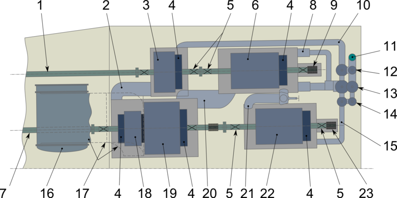
General arrangement of port engine room 1 — outlet shaft; 2 — exhaust trunk from high pressure (HP) for low pressure (LP) astern turbine; 3 - HP astern turbine; 4 — dummy piston; 5 — rotor shaft bearings; 6 — LP ahead turbine; 7 — inner shaft; 8 — main steam to HP ahead turbine; 9 — thrust block; 10 — main steam to HP ahead turbine; 11 — main steam from boiler room; 12 — astern maneuvering valve; 13 — ahead maneuvering valve; 14 — cruising maneuvering valve; 15 — main steam to cruising turbine; 16 — main condenser; 17 — exhaust to condenser; 18 — LP astern turbine; 19 — LP ahead turbine; 20 — exhaust trunk from HP for LP ahead turbine; 21 — exhaust trunk from cruising to HP ahead turbine; 22 — cruising turbine.
File history
Click on a date/time to view the file as it appeared at that time.
| Date/Time | Thumbnail | Dimensions | User | Comment | |
|---|---|---|---|---|---|
| current | 18:57, 21 October 2018 | | 2,155 × 1,078 (219 KB) | General arrangement of port engine room 1 — outlet shaft; 2 — exhaust trunk from high pressure (HP) for low pressure (LP) astern turbine; 3 - HP astern turbine; 4 — dummy piston; 5 — rotor shaft bearings; 6 — LP ahead turbine; 7 — inner sha... |
- You cannot overwrite this file.
File usage
The following page links to this file: